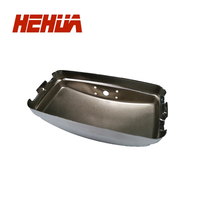
Deep drawing shells are often used where a flat metal blank needs to become a deeper three-dimensional component with controlled dimensions and a stable wall structure. For OEM parts, the challenge is not simply forming the material into a shell. The tooling must control material flow, drawing depth, wall thickness, springback, dimensional accuracy, and the transition between forming operations. These requirements become more important when the part needs to move from sampling into repeatable mass production.
For this type of work, Progressive Die Stamping can combine several operations within a controlled production sequence. With the right material, die structure, and forming strategy, blanking, drawing, bending, and other forming steps can be integrated into a continuous process.
Material selection is one of the first decisions that affects deep drawing performance. Different metals have different levels of ductility, work-hardening behavior, yield strength, and resistance to cracking during forming.
Cold rolled steel can be suitable for many general stamped components, while galvanized steel may be selected when corrosion resistance is required as part of the finished component. Stainless steel such as 304 or 316 provides corrosion resistance but requires careful attention to forming conditions because of its higher strength and work-hardening characteristics. Aluminum offers lower density and can be useful where weight reduction is important.
For deeper shells, special drawing steel deserves particular attention. Its forming characteristics can make it more suitable for applications where the material must flow significantly without developing cracks or excessive thinning.
Copper is also available for suitable stamping applications, depending on the component geometry and required properties. The important point is that material selection should be made together with the intended forming sequence rather than treated as a separate purchasing decision.
A deep drawing operation forces a flat blank into a die cavity, causing the material to flow from the flange area toward the formed wall. If the geometry is too aggressive for a single operation, excessive deformation can result in cracking, wrinkling, or uneven wall thickness.
This is where progressive tooling design becomes important. Instead of trying to achieve the final geometry immediately, the forming sequence can distribute deformation across multiple stations. A production sequence may begin with blanking and then introduce controlled forming or drawing stages before subsequent operations complete the component.
The number and arrangement of stations should be determined by the actual part geometry. Features such as corners, radii, openings, beads, flanges, and changes in diameter can all influence how material needs to move through the die.
WithProgressive Die Stamping, the objective is not simply to place more operations into one tool. Each station needs to perform a defined function while maintaining proper strip progression and part positioning. Poorly planned station sequences can create cumulative dimensional errors even when individual forming operations appear acceptable.
For shell-type components, wall thickness is often more important than simply achieving the outside dimensions. Excessive thinning can reduce mechanical strength, while uncontrolled thickening may interfere with assembly or create dimensional problems.
The supplied stamping capability supports deep drawing wall thickness deviation of up to 5%. In practical production, this requires attention to blank size, punch and die clearance, drawing radius, material properties, lubrication, and the amount of deformation introduced at each stage.
The bottom of a drawn shell may behave differently from the sidewall, so inspection should not be limited to one easily accessible dimension. Critical sections should be identified during the engineering review and then checked during sampling and production.
This is particularly relevant for pressure shells and other formed components where wall consistency affects the functional performance of the finished part.
Deep drawing quality is strongly connected to tooling design. Punch geometry, die radius, clearance, guiding, strip layout, and the relationship between individual stations all influence the final result.
Self-owned molds provide a practical advantage during development because tooling decisions can be evaluated alongside the production process. For OEM and ODM projects, engineers can review customer drawings before production and identify features that may create unnecessary forming difficulty.
The drawing format does not need to be limited to a single CAD system. 2D CAD drawings and 3D files such as STEP, IGS, and SolidWorks formats can be reviewed, while physical samples can also be used as the basis for reverse engineering.
A useful DFM review should look beyond whether the part can theoretically be stamped. It should consider whether the proposed geometry can be produced consistently, whether the number of forming stages is reasonable, whether critical dimensions can be inspected, and whether the design can move efficiently from prototype to repeat production.
Deep drawing and precision stamping are closely connected to dimensional control. A shell can have the correct overall height while still failing because of an incorrect diameter, uneven flange, distorted opening, or excessive flatness variation.
The available stamping tolerance range is ±0.008 to ±0.03 mm, with flatness controlled to ≤0.02 mm for applicable precision components. These figures should not be treated as a universal requirement for every stamped part. Instead, tolerances should be assigned according to the actual function of each feature.
For example, an assembly interface may require tighter control than a non-functional outer surface. Defining these priorities during engineering review can help prevent unnecessary manufacturing difficulty while keeping important dimensions stable.
For production verification, CMM inspection and 100% checking of key dimensions provide additional control. A complete inspection report also gives OEM customers traceable dimensional information rather than relying only on visual inspection or random measurements.
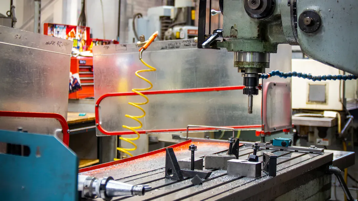
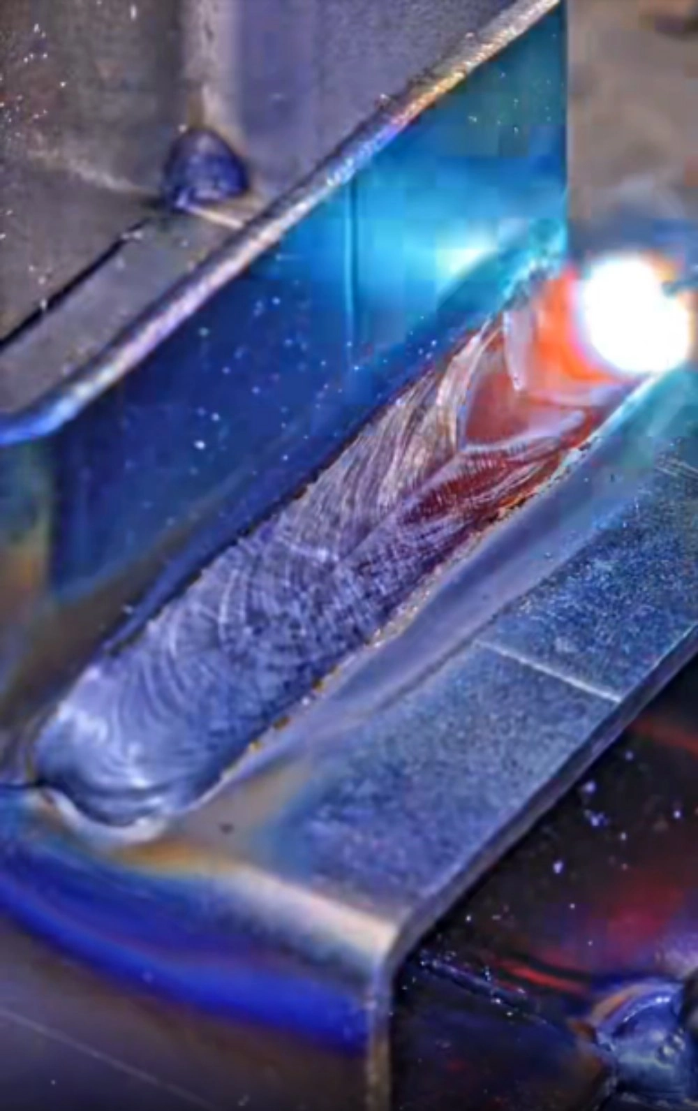
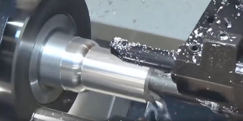
Deep drawing is rarely the only operation required for a finished industrial component. Depending on the design, a stamped shell may require CNC machining, welding, deburring, cleaning, coating, plating, or another surface treatment after forming.
This is why an integrated manufacturing route can be more practical than treating stamping as an isolated process. A part may begin with mold development and sampling, proceed through progressive forming, and then move into secondary machining or welding before receiving its final surface treatment.
For OEM projects, coordinating these steps also reduces the risk of dimensional problems appearing after the stamping stage. For example, a welding operation can introduce distortion, while machining may remove material from a surface that was previously used as a forming reference.
A one-stop production route allows these factors to be considered earlier rather than discovered after the component has already entered mass production.
A short sampling cycle is particularly useful for deep drawing components because many forming problems become obvious only after the actual material and tooling are used.
During the sample stage, engineers can examine cracking, wrinkles, wall thickness, springback, dimensional stability, and the interaction between forming stations. If necessary, the die structure or drawing sequence can then be adjusted before the production quantity increases.
For OEM customers developing new equipment, this process is also useful when replacing an imported part or manufacturing a non-standard component from an existing physical sample. Reverse engineering combined with drawing review can help establish a practical manufacturing route before committing to larger production volumes.
The best process depends on the geometry, material, production volume, tolerance requirements, and downstream operations. A relatively simple shallow component may not require a complex progressive tool. A deeper shell with several additional features, however, may benefit from a carefully planned multi-station process.
Typical applications include compressor accessories, pneumatic components, construction machinery hardware, precision brackets, shims, pressure-related shells, and other special-shaped industrial parts.
For these applications, Progressive Die Stamping should be evaluated as part of the complete manufacturing system rather than as a standalone punching operation. Tooling, material selection, forming sequence, inspection, and finishing all influence the final component.
Hehua Machinery Technology (Kunshan) Co., Ltd. provides OEM and ODM metal stamping services supported by an in-house mold workshop and precision presses ranging from 63T to 315T. Its production capabilities cover blanking, bending, deep drawing, and forming, with supporting CNC machining, welding, and surface treatment.
The company operates a plant of more than 17,800 square meters and has more than 160 employees. Its quality systems include ISO 9001 and IATF 16949 certification, with engineering support covering product development through manufacturing and export. For customers requiring controlled production of deep drawing shells, the combination of engineering review, tooling development, precision forming, and inspection provides a practical route from drawing or sample to repeatable production.
Ultimately, successful shell forming depends on making the right decisions before the press starts running. Material behavior, drawing depth, wall thickness, tooling sequence, tolerance requirements, and inspection criteria should all be considered together. When these factors are properly planned, Progressive Die Stamping can provide a controlled manufacturing route for complex deep-drawn industrial components while supporting the consistency required for OEM production.


 AddressNo. 66 Xingpu Road, Lujia Town,Kunshan City, Factory Buildings 3 and 4
  en
en
 English
 繁体中文
繁体中文 Italian
 Spanish
 Japanese
 Portuguese
 Korean
 Russian
 French
 German
 Estonian
 Arabic
 Indonesian


 Message