Complex CNC bending is not just a matter of selecting the correct bend angle and running a press brake. When a sheet metal component contains multiple bends, short flanges, narrow channels, mounting holes, or enclosed sections, its final accuracy depends heavily on how the part is designed before production begins. A design that looks correct in a CAD model may still cause tool interference, dimensional variation, surface damage, or assembly problems on the shop floor.
For equipment manufacturers, these issues can become more serious when a component must fit precisely into a cabinet, chassis, protective housing, or welded assembly. Designing with manufacturing constraints in mind helps reduce trial adjustments and makes the transition from prototype to mass production more predictable. With an appropriate Bending process and early engineering review, complex sheet metal geometries can be made more consistently without unnecessary redesign.
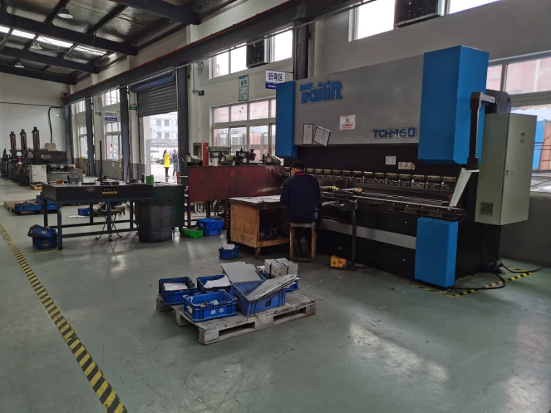
The bend sequence determines how a flat sheet is formed into its final three-dimensional shape. In a simple bracket, the order may be straightforward. In a part with several flanges, return bends, or narrow channels, however, one completed bend may block access to another bend line.
Designers should consider the movement of the sheet, the press brake tooling, and the space required for the machine and operator. A flange that appears harmless in a 3D model may collide with the punch or machine structure during a later operation. Deep channels and box-like shapes may also restrict tool access.
Before releasing a drawing, review the intended forming sequence and identify potential interference points. Where possible, maintain enough clearance between adjacent features to allow the selected tooling to reach each bend line. If a component cannot be formed in one practical sequence, consider whether a different bend order, specialized tooling, or a revised part structure would be more suitable.
At Hehua Machinery Technology (Kunshan) Co., Ltd., engineering review can help identify bending interference and forming risks before production. Reviewing the manufacturing sequence early is especially useful for equipment enclosures, mounting structures, and multi-bend precision components.
The inside bend radius affects material strain, dimensional consistency, and the appearance of the finished part. A radius that is too small for the selected material and thickness can increase the risk of cracking, particularly when forming harder materials or bending across an unfavorable grain direction.
Designers should avoid specifying an unnecessarily tight radius simply to achieve a compact appearance. Instead, the radius should be selected according to the material grade, sheet thickness, forming method, and functional requirements. Stainless steel, galvanized steel, cold-rolled steel, and aluminum may respond differently under similar bending conditions.
For projects using sheet thicknesses from 0.5 mm to 12 mm, the appropriate radius and tooling should be evaluated for each material and geometry. Thin sheets may require careful handling to prevent visible marks or distortion, while thicker sheets may demand greater forming force and sufficient clearance around the bend.
When a drawing specifies a radius that is difficult to manufacture, engineers should assess whether a small design adjustment can preserve the component's function while improving formability. This review can prevent cracking, inconsistent angles, and repeated production adjustments.
A flat pattern cannot always be calculated by adding the outside dimensions of the finished part. During bending, material near the bend line undergoes deformation, so the flat layout must account for the bend allowance or bend deduction used in the unfolding calculation.
The correct calculation depends on factors such as material thickness, inside radius, bend angle, and the neutral axis location. Using an unsuitable bend factor can produce a flat blank that is too long or too short, causing the final flange dimensions to fall outside the drawing requirements.
Springback adds another variable. After the forming force is removed, the material tends to recover part of its deformation, changing the final bend angle. The amount varies with material properties, thickness, radius, and the forming method.
For complex components, the flat pattern should be validated against the actual material and production process rather than relying exclusively on generic CAD settings. Prototype forming can reveal whether the bend factor or compensation value needs adjustment. Once validated, these settings should be controlled during repeat production.
A well-managed Bending process combines drawing review, suitable tooling, forming trials where necessary, and inspection of the resulting dimensions. These steps are particularly important when several bends interact to determine the final position of a mounting face or assembly interface.
Holes, slots, notches, and cutouts located too close to a bend line can deform during forming. Depending on their size and position, they may become oval, shift from their intended location, or create local stress concentrations.
Where a hole must remain dimensionally accurate, designers should provide sufficient distance from the bend zone. The required clearance depends on material thickness, hole geometry, bend radius, and the forming method, so a universal spacing rule should not replace engineering review.
If the design does not allow enough clearance, alternative approaches may include relocating the feature, changing the flange geometry, or adding the hole after bending when the application and production sequence permit it. However, secondary machining adds another operation and should be assessed for accuracy, access, and cost efficiency.
Designers should also check the relationship between holes on different faces. A pattern that is easy to laser-cut on a flat blank may become difficult to inspect after multiple bends. Datums and dimensions should be chosen to reflect how the finished part will be located and assembled, not only how it appears in the original drawing.
Short flanges can be challenging because the tooling may not have enough material to form the bend reliably. Conversely, long flanges can interfere with other features as the sheet rotates during forming. These limitations become more important in narrow channels, offset bends, and compact enclosures.
Before production, check minimum flange lengths against the selected tooling and material thickness. Confirm that the punch and die can reach the intended bend line without colliding with an adjacent wall or previously formed section. For parts with multiple bends, the clearance should be evaluated throughout the forming sequence rather than only in the final shape.
Designers should also consider the space required for assembly. Two parts may each meet their individual drawing dimensions but still interfere when installed together if the design provides insufficient clearance for manufacturing variation.
For cabinets, compressor enclosures, protective housings, and precision equipment frames, reviewing these relationships early can reduce fitting problems during final assembly. A practical design should accommodate both the nominal geometry and the expected variation in production.
Applying very tight tolerances to every dimension can make sheet metal production unnecessarily difficult. Instead, tolerances should reflect the function of each feature. Mounting holes, mating surfaces, locating points, and interfaces with machined components may require tighter control than non-functional edges or cosmetic features.
A tolerance scheme should also account for cumulative variation. In a multi-bend component, small deviations in several bend angles can shift the position of a final flange or hole pattern. Measuring each bend independently may not be sufficient if the overall assembly dimension is the critical requirement.
For suitable parts, Hehua Machinery Technology (Kunshan) Co., Ltd. supports CNC bending dimensional tolerances of approximately ±0.05 to ±0.1 mm and bend angle tolerances of ±0.5°, depending on part geometry, material, and process conditions. These values should be confirmed against the actual drawing and application during engineering review.
First-article inspection, in-process checks, and focused inspection of critical bend dimensions help verify that the finished component matches its requirements. Where necessary, coordinate measuring equipment and documented inspection results can support dimensional verification before shipment.
A sheet metal component rarely exists as an isolated bent part. It may later be welded, riveted, fastened, coated, or assembled with machined components. These downstream processes can affect the final geometry and should be considered during the design stage.
For example, welding can introduce distortion, while thick coatings may affect clearances between mating parts. Brushed or exposed surfaces may also require additional handling precautions to avoid scratches and visible tooling marks. If corrosion resistance is important, the selected material and finishing method should match the component's operating environment.
Specify surface treatments according to function and appearance. Options may include powder coating, brushing, anodizing, polishing, plating, and other protective finishes, depending on the material and application. Designers should identify cosmetic surfaces and functional contact areas clearly so that manufacturing and inspection teams understand which features require special attention.
A coordinated process covering laser cutting, CNC bending, riveting, welding, and finishing helps maintain consistency across the completed assembly. It also reduces the risk of discovering design conflicts only after a component has reached a later production stage.
A manufacturable design needs more than a 3D model. Production teams should receive clear material specifications, thickness, bend radii, dimensional tolerances, hole positions, surface finish requirements, and assembly references. The drawing package should also identify critical-to-function dimensions and any special inspection requirements.
Common design formats such as CAD drawings and 3D STEP, IGS, SolidWorks, or UG files can support engineering review. A complete drawing package allows the manufacturing team to assess the flat pattern, forming sequence, potential interference, and inspection method before committing to a production plan.
Prototype validation is particularly valuable for complex geometries. A first sample can confirm whether the part forms as intended, whether holes and mounting faces align, and whether the component fits with adjoining parts. Any required changes to the bend sequence, springback compensation, or tolerance scheme can then be incorporated before mass production.
Hehua Machinery Technology (Kunshan) Co., Ltd. provides integrated sheet metal fabrication services covering design-for-manufacturing review, laser cutting, CNC bending, forming, welding assembly, and surface treatment. With a plant exceeding 17,800 square meters, more than 160 employees, and quality systems including ISO 9001 and IATF 16949, the company supports projects for industrial machinery, automotive, rail transit, new energy equipment, and other high-end manufacturing applications.
Complex CNC bending parts are easier to manufacture when the design accounts for material behavior, bend sequence, tool access, dimensional tolerances, and downstream assembly requirements. Early review can identify problems that might otherwise lead to repeated prototypes, rework, or inconsistent production results.
When preparing a new sheet metal component, share the 2D drawings and 3D files with the manufacturing team and identify the dimensions that matter most to fit and function. A practical Bending solution should connect design intent with verified forming methods, inspection criteria, and repeatable production controls. By working with Hehua Machinery Technology (Kunshan) Co., Ltd. from the design review stage, equipment manufacturers can improve manufacturability and build a more reliable path from prototype approval to batch production.


 AddressNo. 66 Xingpu Road, Lujia Town,Kunshan City, Factory Buildings 3 and 4
  en
en
 English
 繁体中文
繁体中文 Italian
 Spanish
 Japanese
 Portuguese
 Korean
 Russian
 French
 German
 Estonian
 Arabic
 Indonesian


 Message