Dimensional accuracy is a critical requirement in sheet metal manufacturing, especially when fabricated parts must fit together with machined components, mounting brackets, frames, or protective enclosures. Even a small deviation in a bend angle or flange dimension can affect hole alignment, assembly clearance, and the performance of the finished product. For equipment manufacturers sourcing custom metal parts, understanding CNC bending tolerances helps establish realistic drawing requirements and reduce production problems before they occur.
Bending is an important part of precision sheet metal fabrication because it transforms flat metal sheets into functional three-dimensional components. The achievable accuracy depends on more than the bending machine itself. Material properties, sheet thickness, tooling selection, bend geometry, springback, and inspection methods all influence the final dimensions. By addressing these factors during design and production, manufacturers can improve repeatability and maintain consistent quality across prototype and mass-production orders.
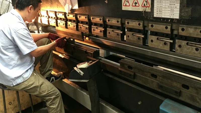
CNC bending tolerances define the acceptable variation between the dimensions specified in a technical drawing and those measured on a finished bent component. These requirements may apply to flange lengths, overall dimensions, bend angles, hole positions, and the relationship between multiple bends.
For example, a sheet metal bracket may require two perpendicular flanges and accurately positioned mounting holes. If the bend angle is slightly outside the specified range, the bracket may not sit flush against its mating component. If the flange length deviates, the mounting holes may no longer align correctly.
Different dimensions require different tolerance considerations. Linear tolerances control distances and overall geometry, while angular tolerances determine the accuracy of each bend. Flatness and perpendicularity may also matter when a component must be installed against a reference surface.
For precision sheet metal parts, tolerance requirements should be defined according to the component's function rather than making every dimension unnecessarily tight. This approach helps balance manufacturing feasibility, inspection requirements, and assembly performance.
The appropriate tolerance depends on the material, thickness, part geometry, tooling, and production conditions. A tolerance that is achievable on a straightforward bracket may be more difficult to maintain on a large enclosure with several bends.
In Hehua's sheet metal fabrication process, the stated CNC bending dimensional tolerance is ±0.05–±0.1 mm, with a bending angle tolerance of ±0.5°. These figures provide a useful reference for discussing precision requirements, but the applicable tolerance for a specific part should be confirmed through drawing review and process evaluation.
Several factors should be considered when specifying tolerances:
l Linear dimensions: Flange lengths and overall dimensions depend on positioning accuracy, tooling setup, material behavior, and the measurement reference.
l Bend angles: Angle accuracy is affected by springback, material variation, machine compensation, and the consistency of the bending process.
l Multiple bends: Dimensional deviations can accumulate across a sequence of bends, affecting the final shape and assembly fit.
l Flatness and alignment: Large panels and formed enclosures may require additional controls to ensure that mounting surfaces remain suitable for assembly.
A clear drawing should identify critical dimensions and indicate which features directly affect assembly. This allows the manufacturing team to focus process controls and inspection resources where they have the greatest impact.
Different metals respond differently to bending forces. Cold-rolled steel, galvanized steel, stainless steel, and aluminum have different strength, ductility, and elastic recovery characteristics.
Stainless steel often exhibits noticeable springback, while aluminum alloys may require careful attention to cracking risks and bending direction. Thicker sheets generally require greater bending force and suitable tooling, while thin sheets may be more susceptible to surface marks or local deformation.
Bending process parameters should therefore be selected according to the actual material grade and thickness rather than relying on a single setup for every sheet. Material traceability and consistent incoming inspection also help reduce variation between production batches.
Punch geometry, die opening, and inside bend radius influence the shape and dimensions of the finished part. Incorrect tooling selection can cause excessive deformation, cracking, inconsistent angles, or dimensional deviations.
The bend radius must be compatible with the material and design requirements. A radius that is too small may increase the risk of cracking, while an unsuitable die opening can affect the required bending force and the resulting geometry.
For components with narrow flanges, closely spaced bends, or complex profiles, engineers should review tool access and potential interference before production begins.
Springback occurs when a metal sheet partially returns toward its original shape after the bending force is released. The amount varies according to material properties, thickness, bend radius, and forming conditions.
If springback is not adequately compensated for, a nominal 90-degree bend may finish at a different angle. This can create alignment problems in enclosures, mounting brackets, and multi-bend assemblies.
Practical controls include trial bending, angle measurement, parameter adjustment, and compensation based on the observed behavior of the material. For repeat orders, recording validated process settings helps maintain consistency and reduces the need for repeated setup adjustments.
The order in which bends are formed can affect both dimensional accuracy and production feasibility. On complex components, a previous flange may obstruct the tooling required for a later bend. Poorly planned sequences can also make accurate positioning more difficult.
Designers should review flange lengths, hole locations, bend reliefs, and clearances between formed features. When multiple bends interact, checking the flat pattern and the three-dimensional model together can help identify potential problems before the first part is produced.
Consistent accuracy requires coordinated control across engineering, machine setup, and inspection. Relying only on the bending machine's programmed dimensions does not guarantee that every finished component will meet the drawing.
First, engineers should review the supplied CAD models and technical drawings before production. This review can identify bend interference, insufficient flange lengths, unsuitable radii, and dimensions that may be difficult to achieve with the selected material.
Second, the production team should verify the initial setup using a first article. Critical flange dimensions and bend angles should be measured before the same program and tooling arrangement are applied to the remaining batch. If deviations appear, the bending parameters or compensation values can be adjusted before more parts are produced.
Third, in-process inspection should focus on dimensions that directly affect fit and function. For complex assemblies, checking the relationship between multiple bends is often as important as measuring each individual flange.
Finally, measurement results and process adjustments should be documented. Consistent records make it easier to investigate recurring deviations, compare production batches, and maintain repeatability when a part is reordered.
A well-prepared drawing helps the manufacturer determine whether the specified tolerances are achievable and which production controls are necessary. Two-dimensional CAD drawings and three-dimensional STEP, IGS, SolidWorks, or UG files can provide complementary information about dimensions, bend geometry, and assembly relationships.
Before manufacturing starts, the engineering team should confirm the material grade, sheet thickness, bend radius, critical dimensions, surface finish, and inspection requirements. Any unclear or conflicting specifications should be resolved before the drawing is released for production.
For new designs, prototype validation is particularly useful. A sample allows the customer to verify dimensions and assembly fit under actual manufacturing conditions. Design or process adjustments can then be made before moving into small-batch or mass production.
This process is especially relevant to equipment cabinets, compressor enclosures, precision instrument housings, construction machinery guards, and new energy equipment enclosures, where several formed panels and mounting features must work together.
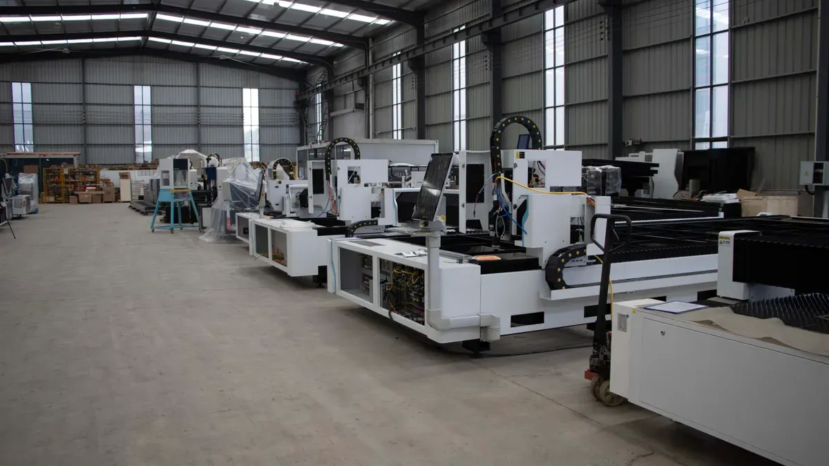
Hehua Machinery Technology (Kunshan) Co., Ltd. provides sheet metal fabrication services for industrial equipment and other demanding manufacturing applications. Its capabilities cover laser cutting, CNC bending, punching, riveting, welding, grinding, straightening, and surface finishing, supporting projects from prototype development through small-batch trials and mass production.
The company processes sheet materials from 0.5 mm to 12 mm, including SPCC cold-rolled steel, galvanized steel, 304 and 316 stainless steel, and aluminum. Depending on the project, finishing options include powder coating, brushing, anodizing, polishing, and other treatments designed to meet functional and appearance requirements.
For precision work, the manufacturing process incorporates drawing review, first-article inspection, in-process checks, and dimensional verification of critical bending features. Coordinate measuring machine (CMM) inspection and dimensional reports can support projects that require documented verification. Material traceability and additional testing can also be arranged according to the component's specifications.
Established in 2018 as a subsidiary of Shanghai Hehua Machinery Technology Co., Ltd., the Kunshan company operates within a manufacturing organization with a plant area exceeding 17,800 square meters and more than 160 employees. The wider organization serves industries including automotive, rail transit, aerospace, wind power, industrial machinery, semiconductor equipment, and new energy equipment.
Its quality systems include ISO 9001 and IATF 16949 certification, while EN 15085 certification supports its rail vehicle welding operations. These systems provide a structured framework for manufacturing control, although the inspection plan and acceptance criteria for each sheet metal part should still be defined according to its drawings and application.
The most suitable CNC bending tolerance is the one that reliably supports the component's intended function without imposing unnecessary manufacturing complexity. Tight tolerances are important for mounting interfaces, precision enclosures, and multi-part assemblies, but less critical dimensions may allow wider variation.
Before requesting a quotation, buyers should provide clear drawings, material specifications, thickness requirements, surface treatment details, and any critical inspection criteria. Identifying functional dimensions early allows the engineering team to evaluate the forming process and recommend practical production controls.
For custom sheet metal components requiring consistent geometry and reliable assembly,Bending should be evaluated as part of the complete fabrication process rather than as an isolated operation. Coordinating design review, material selection, forming parameters, and inspection helps reduce rework and supports repeatable results from prototype approval to mass production.
To discuss drawing requirements or evaluate a custom sheet metal project, contact Hehua Machinery Technology (Kunshan) Co., Ltd. with your CAD files and technical specifications for an engineering review.


 AddressNo. 66 Xingpu Road, Lujia Town,Kunshan City, Factory Buildings 3 and 4
  en
en
 English
 繁体中文
繁体中文 Italian
 Spanish
 Japanese
 Portuguese
 Korean
 Russian
 French
 German
 Estonian
 Arabic
 Indonesian


 Message