Welding distortion is one of the most common challenges in manufacturing metal assemblies. Even when individual components are cut and formed to the correct dimensions, heat generated during welding can cause plates to bend, frames to twist, and mounting surfaces to shift out of position. These changes may seem minor at the welding stage, but they can create significant problems during subsequent machining, component installation, and final equipment assembly.
For industrial machinery manufacturers, maintaining dimensional accuracy requires more than controlling the MIG welding operation itself. Fixture design, joint preparation, welding sequence, material properties, and post-weld correction all influence the final result. A well-planned manufacturing process must address these factors before production begins.
At Hehua Machinery Technology (Kunshan) Co., Ltd., welding distortion control is integrated into custom metal fabrication, from drawing evaluation and fixture development to welding, straightening, CNC secondary machining, and final inspection. Understanding how these processes work together helps manufacturers produce more consistent welded assemblies for demanding industrial applications.
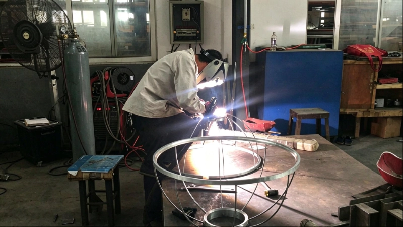
MIG welding uses an electric arc to melt the base material and filler wire, creating a metallurgical bond between metal components. The localized heating and subsequent cooling generate uneven thermal expansion and contraction. Because different areas of a workpiece experience different temperature changes, internal stresses develop throughout the welded structure.
Several types of distortion can occur during this process:
l Angular distortion: Uneven contraction across a joint causes connected plates to rotate relative to each other.
l Longitudinal shrinkage: Weld metal contracts along the length of the weld, potentially shortening the assembly.
l Transverse shrinkage: Contraction across the weld joint pulls connected components closer together.
l Bowing and bending: Uneven heat distribution causes long plates, beams, or frames to curve.
l Twisting: Asymmetrical weld placement and uneven shrinkage cause the assembly to rotate or lose alignment.
The risk increases when welding thin sheet metal, long structural members, or assemblies containing multiple interconnected components. Material thickness, joint geometry, welding parameters, and the total weld length all influence the degree of deformation.
For example, a compressor frame with multiple welded mounting brackets may develop local angular distortion if the brackets are welded continuously from one side. Even if the welds are structurally sound, the resulting misalignment can make it difficult to install motors, housings, or other equipment.
This is why distortion prevention needs to be considered during the engineering and fixture design stages rather than relying entirely on correction after welding.
A welding fixture establishes the position of individual components and maintains their relationship throughout the welding operation. Its primary function is to prevent unwanted movement, but effective fixture design must also account for thermal expansion and contraction.
Simply applying more clamping force does not necessarily improve accuracy. Excessive restraint can increase residual stress and may cause additional deformation when the workpiece is released. The objective is to control movement without unnecessarily restricting the natural thermal behavior of the material.
Several fixture design factors are particularly important.
Accurate locating points
Locating pins, reference surfaces, and positioning blocks establish the initial geometry of the assembly. Their positions should correspond to important drawing dimensions and functional mounting surfaces.
For equipment frames and precision brackets, locating points should be selected based on the final assembly requirements. This reduces the possibility of accumulating dimensional errors between multiple welded components.
Appropriate clamping positions
Clamps should be positioned close enough to the welding area to prevent component movement, but their arrangement must also consider heat distribution and access to the weld joint.
For large frames, distributed clamping is generally more effective than concentrating restraint in a few locations. The fixture should provide sufficient rigidity while allowing practical access for welding operations.
Fixture rigidity and repeatability
A fixture that deforms under clamping forces or repeated thermal exposure can introduce inconsistent results. Its supporting structure should be sufficiently rigid for the workpiece size, weight, and production requirements.
Repeatable positioning is particularly important for batch manufacturing, where small differences in component placement can accumulate into noticeable variations between finished assemblies.
At Hehua Machinery, fixture fabrication is included in the one-stop OEM and ODM welding service. Engineering teams review customer drawings and assess potential deformation risks before production. This allows fixture structures and locating arrangements to be adjusted according to the actual component geometry.
Even with a properly designed fixture, an unsuitable welding sequence can produce uneven heat distribution and excessive shrinkage.
The welding sequence should be planned according to joint arrangement, material thickness, assembly geometry, and the required dimensional tolerances.
Balanced welding
Where the structure permits, welding should be distributed across opposite sides or symmetrical positions. This helps balance shrinkage forces and reduces the tendency for the workpiece to bend in one direction.
For example, when welding two mounting plates onto a structural frame, completing all welds on one side before moving to the other may create uneven contraction. Alternating between corresponding weld locations can help reduce this effect.
Skip welding and staggered welding
For suitable structural joints, skip welding allows separate sections of a weld to be completed at intervals rather than continuously along the entire joint.
Staggered welding distributes heat across different areas and can reduce localized thermal accumulation. However, the selected method must still satisfy the structural strength and sealing requirements of the assembly.
Control of heat input
Welding current, voltage, travel speed, wire feed speed, and welding technique all influence heat input.
Excessive heat can increase the size of the heat-affected zone and intensify material contraction during cooling. Insufficient heat, on the other hand, may lead to incomplete fusion or inadequate penetration.
The correct welding parameters must therefore balance distortion control with the required weld quality.
For MIG Welding, process selection should also consider the material being joined. Carbon steel, stainless steel, and aluminum alloys respond differently to thermal input. A parameter combination suitable for a thick carbon steel frame may not be appropriate for a thin aluminum assembly.
Material selection and joint geometry have a direct impact on distortion behavior.
Thin metal sheets are generally more susceptible to warping because they have less structural stiffness. Long, narrow components may also bend easily when welding is concentrated along one edge.
Thicker sections provide greater resistance to certain types of deformation, but they may require higher heat input and more extensive welding operations. This can increase residual stress and complicate dimensional control.
Joint design should therefore be evaluated before production.
For example:
l Butt joints require appropriate alignment and root preparation to achieve consistent fusion.
l Fillet joints should have suitable weld sizes to meet load requirements without unnecessary weld metal deposition.
l Overlapping joints need proper positioning to avoid gaps and inconsistent fit-up.
l Multi-joint structures should be arranged to distribute welding stresses as evenly as practical.
The use of unnecessary oversized welds can increase heat input without providing a meaningful improvement in structural performance. Matching weld dimensions to actual engineering requirements helps control both material consumption and deformation.
Hehua supports carbon steel, galvanized steel, 304/316 stainless steel, aluminum alloy, cast iron, ductile iron, and copper alloy welding. The welding process and joint arrangement are evaluated according to material characteristics, plate thickness, load requirements, and the intended application.
Preventive measures can significantly reduce welding distortion, but they cannot eliminate every dimensional deviation. Complex structures may still require post-weld correction to meet final drawing requirements.
Straightening is used to restore the geometry of welded components after cooling. Depending on the part structure, correction may involve mechanical pressing, localized adjustment, or other controlled straightening methods.
The process must be carefully managed. Excessive correction forces can introduce additional deformation or damage the welded structure. Critical mounting surfaces and reference dimensions should be checked before and after straightening.
For equipment bases and compressor frames, flatness and mounting alignment are particularly important. A base that does not sit correctly may transfer unwanted stress to connected components during installation.
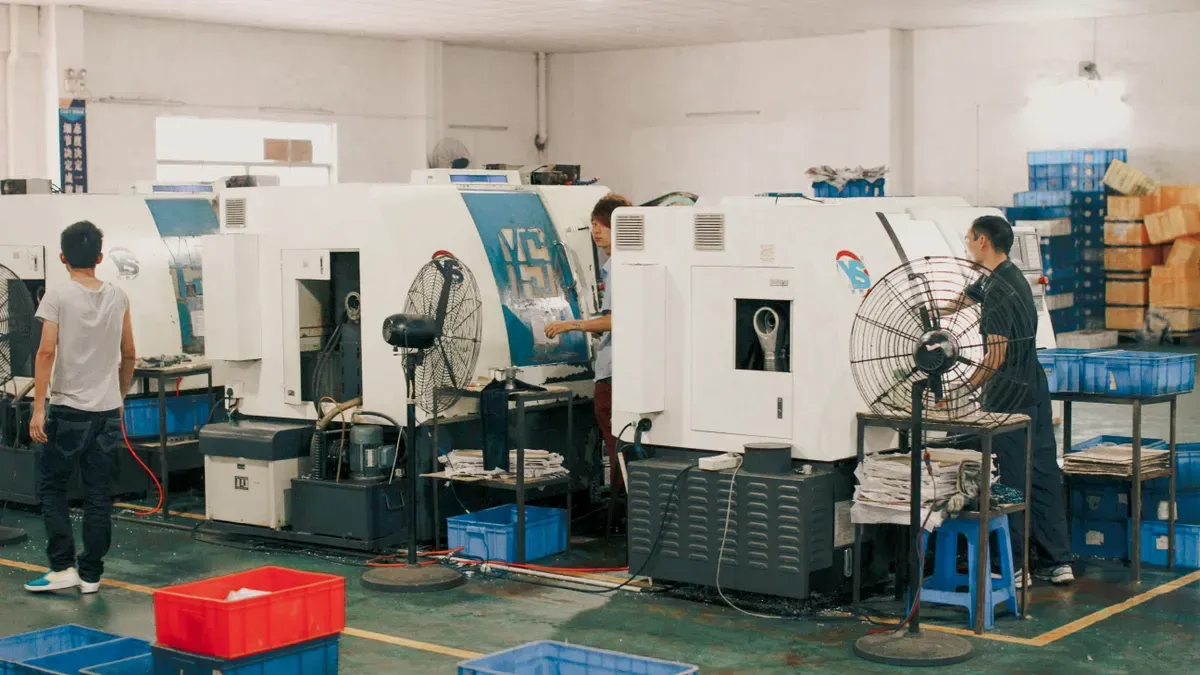
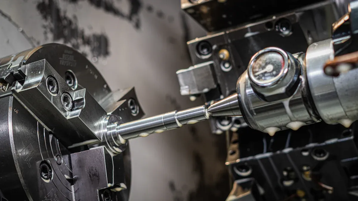
CNC secondary machining can provide an additional level of dimensional control. After welding and straightening, selected mounting holes, contact surfaces, or precision interfaces can be machined to meet assembly requirements.
This integrated process is particularly useful when welded structures contain both load-bearing sections and precision-machined features.
At Hehua Machinery Technology (Kunshan) Co., Ltd., the manufacturing process can include blanking, fixture fabrication, welding, straightening, CNC secondary machining, and surface finishing. The stated post-straightening flatness capability reaches ≤0.03 mm/100 mm, depending on part geometry and processing conditions.
A reliable distortion control process needs measurable inspection criteria. Visual assessment alone cannot confirm whether an assembly meets its dimensional requirements.
Several inspection stages help identify deviations before they affect subsequent production.
First-article dimensional inspection
The first completed assembly should be checked against the approved drawings. Important dimensions include overall length and width, mounting hole positions, frame squareness, flatness, and critical interface locations.
Identifying deviations at this stage allows fixture positioning or welding parameters to be adjusted before batch production continues.
In-process inspection
Periodic dimensional checks help determine whether the welding process remains stable. For repetitive production, monitoring the same reference dimensions across different batches can reveal gradual fixture wear or process variation.
Weld quality inspection
Weld appearance inspection helps identify visible defects such as cracks, surface porosity, and incomplete weld profiles. For critical applications, additional non-destructive testing methods may be required.
Magnetic particle testing (MT) and ultrasonic testing (UT) are available for appropriate welded components. Pressure-related assemblies can also undergo air tightness and hydrostatic testing according to their application requirements.
Hehua maintains a quality control process covering incoming material inspection, in-process checks, post-weld straightening, and final dimensional verification. The company is ISO 9001 certified, and its welding quality management capabilities are supported by IATF 16949 and EN 15085 certifications. Its qualified welders hold EN ISO 9606-1 qualifications.
For OEM manufacturers, welding accuracy depends on the coordination of engineering, production, and quality inspection rather than a single welding operation.
Established in 2005, Hehua has developed metal manufacturing capabilities serving automotive, rail transit, aerospace, wind power, nuclear power, industrial machinery, semiconductor equipment, and new energy equipment industries.
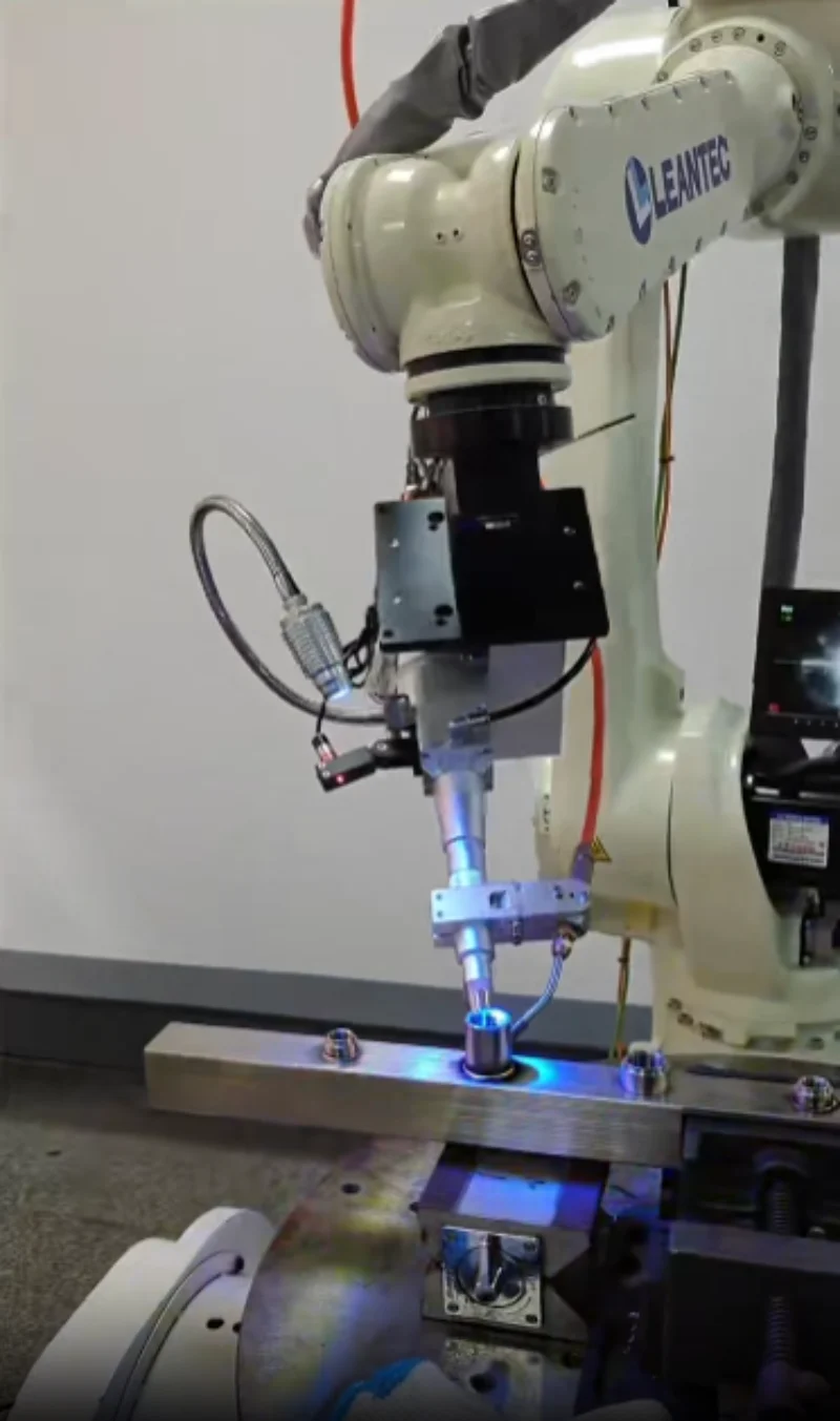
Hehua Machinery Technology (Kunshan) Co., Ltd. operates a manufacturing facility covering more than 17,800 square meters, with over 160 employees and annual sales exceeding RMB 130 million. Its production capabilities combine manual welding stations, robotic welding cells, stamping, CNC machining, cutting, straightening, and surface treatment.
For custom welding projects, the engineering process begins with drawing evaluation. The team reviews 2D CAD drawings and 3D files in formats such as STEP, IGS, SolidWorks, and UG to assess component geometry, joint accessibility, and potential deformation risks.
For customers without complete technical drawings, reverse engineering from physical samples is also available.
Prototype sampling generally takes 3–7 days, allowing customers to evaluate component fit and manufacturing quality before proceeding with mass production. Welding DFM optimization is also available to identify opportunities to improve fixture arrangements, reduce deformation risks, and minimize production rework.
The company operates under ISO 9001, IATF 16949, and EN 15085 quality management requirements, supporting the production of welded components for different industrial applications. Both the parent company and its subsidiary have independent import and export rights, enabling end-to-end manufacturing and export services.
Controlling welding distortion requires a coordinated approach that begins with product design and continues through final inspection. Fixture positioning, clamping strategy, welding sequence, heat input, material selection, and post-weld straightening all contribute to the dimensional accuracy of the finished assembly.
For manufacturers working with equipment frames, compressor structures, machinery brackets, and pressure-related components, these factors directly affect assembly fit, structural reliability, and production consistency.
With integrated engineering support, manual and robotic welding capabilities, CNC secondary machining, and post-weld finishing, Hehua Machinery Technology (Kunshan) Co., Ltd. provides custom MIG Welding and metal fabrication solutions for industrial OEM projects.
Whether the requirement involves prototype development or repeatable batch production, a carefully planned welding process helps reduce dimensional variation and deliver welded assemblies that meet practical manufacturing and application requirements.


 AddressNo. 66 Xingpu Road, Lujia Town,Kunshan City, Factory Buildings 3 and 4
 en
 English
 繁体中文
 Italian
 Spanish
 Japanese
 Portuguese
 Korean
 Russian
 French
 German
 Estonian
 Arabic
 Indonesian



 Message