When a welded metal component needs to fit accurately, withstand mechanical loads, or maintain a sealed structure, weld penetration and joint quality become critical considerations. A weld that looks smooth on the surface may still contain incomplete fusion, internal porosity, or inconsistent penetration. These issues can affect assembly accuracy, structural performance, and the reliability of finished equipment.
For manufacturers sourcing custom metal components, understanding the factors that influence welding results helps prevent design problems before production begins. Material selection, joint preparation, process parameters, fixture design, and inspection methods all contribute to the final outcome. Laser Welding is one option for precision metal joining, particularly when the application requires controlled heat input and consistent weld geometry. Selecting the right process and validating it against actual part requirements are essential steps toward repeatable manufacturing quality.
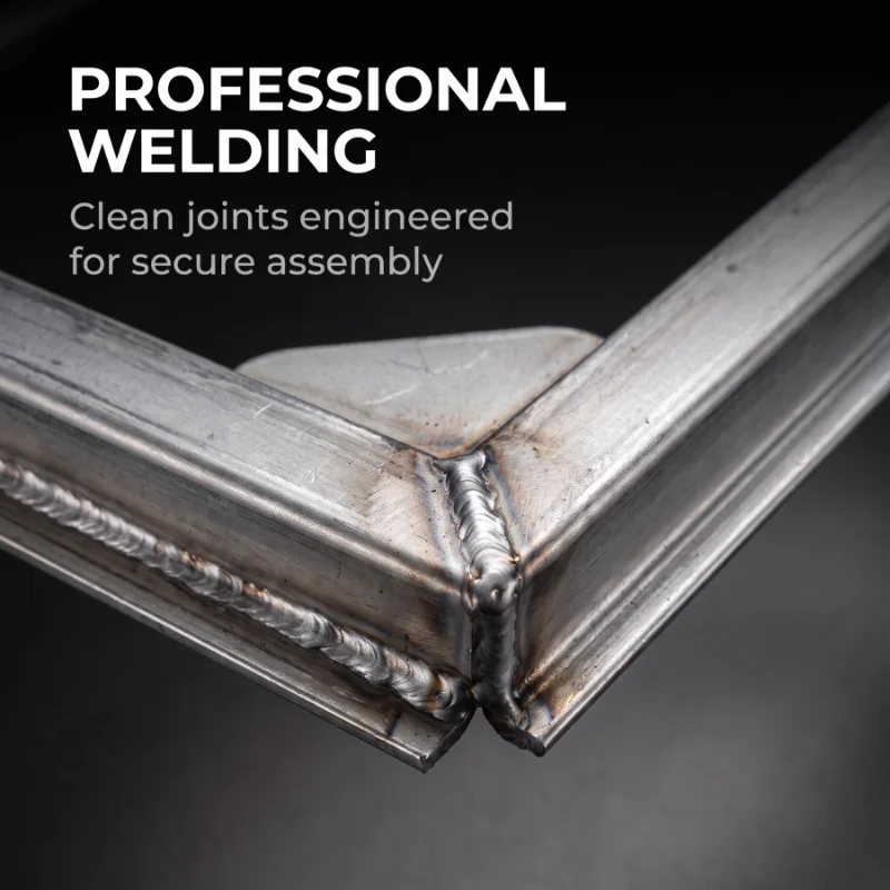
Weld penetration describes how deeply the weld extends into the base material. Depending on the joint design and application, a weld may require partial penetration or full penetration through the joint thickness. The appropriate target depends on the component's structural loads, sealing requirements, material thickness, and applicable engineering specifications.
Insufficient penetration can reduce the effective load-bearing area and create a weak connection between joined parts. Excessive penetration, on the other hand, may cause burn-through, an irregular weld root, or unwanted material distortion. Neither outcome can be evaluated reliably through surface appearance alone.
For industrial equipment frames, mounting brackets, welded housings, and pressure-containing assemblies, penetration requirements should be established during drawing review. Engineers need to identify the critical weld locations, specify the required joint geometry, and determine whether destructive testing, nondestructive testing, or leak testing is necessary.
The choice of Laser Welding should therefore begin with the component's functional requirements rather than the assumption that one welding process is suitable for every metal part.
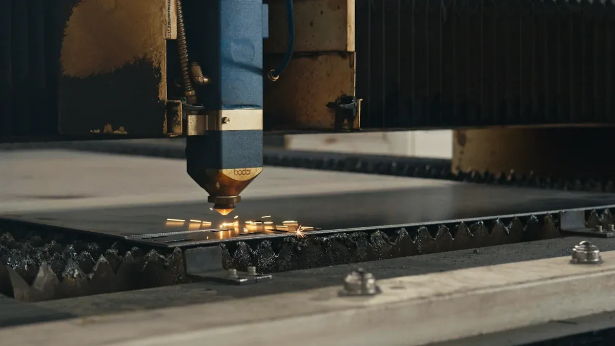
Laser power and travel speed directly influence the amount of energy delivered to the joint. Higher power can increase penetration when other conditions remain suitable, while a higher travel speed generally reduces the energy applied per unit length.
However, increasing power does not automatically improve weld quality. Excessive energy may produce an unstable weld pool, spatter, undercut, or burn-through. Insufficient energy can result in incomplete fusion or a shallow weld that fails to meet the required joint strength.
The relationship between power and speed also changes with material type, thickness, joint configuration, and equipment characteristics. A parameter combination that works for a thin stainless steel sheet may not be suitable for a thicker carbon steel component or an aluminum alloy assembly.
A practical process development procedure should include:
l Establishing the material grade and actual thickness of each component.
l Confirming the joint type, fit-up condition, and required penetration depth.
l Testing an initial range of power and travel speed settings.
l Inspecting weld appearance and measuring penetration on representative samples.
l Recording approved parameters for repeatable production.
For OEM projects, these checks are especially useful before moving from prototype quantities to recurring production batches. A documented welding procedure gives production teams a reference for identifying process deviations and maintaining consistent results.
Different metals respond differently to concentrated heat. Carbon steel, stainless steel, aluminum alloys, galvanized steel, and copper alloys have different thermal properties, surface conditions, and metallurgical characteristics. These differences affect energy absorption, heat flow, weld pool behavior, and the risk of defects.
Stainless steel components, including 304 and 316 grades, are commonly used where corrosion resistance and durability are important. Welding conditions must be controlled to limit distortion and avoid defects that could compromise the component's intended performance.
Aluminum alloys present different challenges because of their high thermal conductivity, reflective surface, and oxide layer. Surface preparation and carefully validated process settings are important for obtaining stable fusion. The specific alloy and component geometry also influence the appropriate procedure.
Galvanized steel requires particular attention to the coating in the weld area. Zinc vapor can contribute to porosity and other weld discontinuities if the joint preparation and process are not properly managed. Suitable controls must also address worker safety and ventilation.
For dissimilar metal joints, material compatibility requires additional engineering evaluation. Differences in melting behavior, thermal expansion, and metallurgical compatibility may create cracking or brittle intermetallic phases. Such combinations should be validated individually rather than assumed to be suitable for direct welding.
Before production starts, the engineering team should confirm material specifications, thickness tolerances, coating conditions, and any requirements for material traceability. These details help determine whether Laser Welding is appropriate or whether another process would provide a more reliable result.
Even well-selected welding parameters cannot compensate for poor joint preparation. Gaps between mating parts, inconsistent edge conditions, oil contamination, oxide layers, and dimensional variation can all affect weld formation.
Joint geometry should be designed around the required penetration, access for the welding head, and the expected loads. Butt joints, lap joints, and other configurations behave differently, so the choice should reflect both the component's function and manufacturing limitations.
Fixture design is equally important. A fixture must position the components accurately and maintain consistent alignment throughout welding. If the parts shift during the process, the weld may deviate from its intended path or produce inconsistent fusion.
Clamping force also needs careful consideration. Excessive restraint can introduce stress or complicate distortion control, while inadequate restraint allows components to move during heating and cooling. The correct approach depends on the geometry, material, and welding sequence.
For complex equipment bases, brackets, and fabricated housings, reviewing the design before production can identify problems such as inaccessible joints, unnecessary weld lengths, difficult clamping positions, and excessive machining allowances.
Hehua Machinery Technology (Kunshan) Co., Ltd. provides integrated manufacturing support that includes drawing review, fixture fabrication, welding, straightening, CNC secondary machining, and surface finishing. This coordinated approach helps address manufacturability issues before they become costly production problems.
Welding introduces localized heat, followed by cooling and contraction. The resulting residual stresses can change a component's flatness, alignment, and overall dimensions. The extent of distortion depends on material thickness, joint arrangement, heat input, clamping conditions, and welding sequence.
Although laser-based processes can offer concentrated heat input, they do not eliminate distortion in every application. Thin sheets, asymmetric structures, and components with long weld seams may still require careful process planning.
Several measures can help improve dimensional stability:
l Use fixtures that provide repeatable positioning without unnecessary restraint.
l Review weld sequence and seam placement to manage uneven heat distribution.
l Verify component dimensions before and after welding.
l Apply straightening where required by the drawing and functional tolerances.
l Perform CNC secondary machining after welding when critical mounting surfaces or interfaces need tighter dimensional control.
Inspection should focus on dimensions that affect the next manufacturing operation or final assembly. For example, a mounting bracket may require accurate hole locations, while an equipment base may need controlled flatness and alignment.
In a multi-process manufacturing workflow, the inspection plan should define when measurements are taken and which operations may change the dimensions. This is more effective than waiting until final inspection to discover that a welded assembly no longer meets its drawing requirements.
Weld quality assessment should combine visual examination with inspection methods suited to the component's function and acceptance criteria. No single method can identify every type of weld defect.
Visual inspection can reveal surface cracks, visible porosity, undercut, irregular weld profiles, and other observable discontinuities. Dimensional inspection confirms whether the completed assembly meets its specified geometry.
For critical welds, additional testing may be required. Magnetic particle testing can help detect surface and near-surface discontinuities in suitable ferromagnetic materials. Ultrasonic testing can identify certain internal discontinuities when the component geometry, material, and procedure are suitable. Cross-section examination of representative samples can help verify penetration and fusion during process development.
Pressure-containing components may also require air leak testing or hydrostatic testing, depending on their design and applicable requirements. These tests address sealing or pressure integrity, but they do not replace all other weld inspections.
An effective quality plan should define acceptance criteria before manufacturing begins. It should also identify inspection frequency, required records, and the treatment of nonconforming parts.
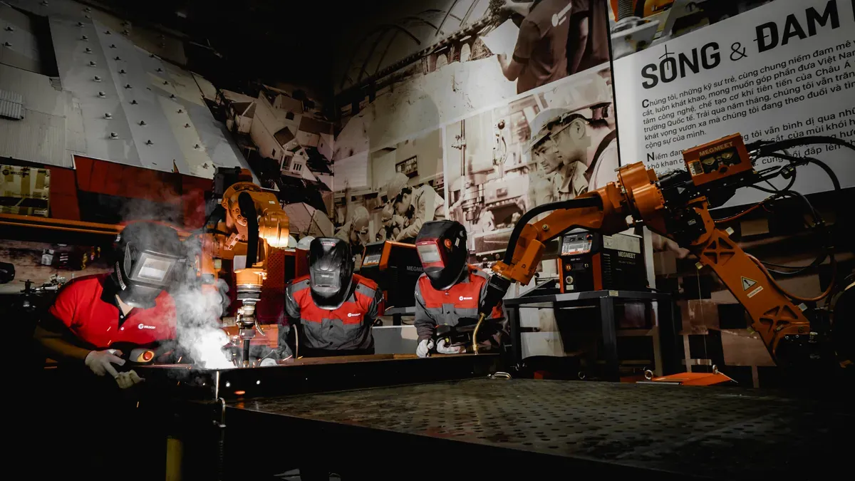
With ISO 9001 and IATF 16949 quality management system certifications and EN 15085 certification for rail vehicle and component welding, Hehua has established quality systems supporting demanding industrial manufacturing applications. Its qualified welders and inspection capabilities help customers align manufacturing controls with project-specific requirements.
Welding is often one stage in a larger manufacturing process. A completed assembly may still require straightening, deburring, CNC machining, grinding, or protective surface treatment before it can be installed in the final equipment.
The sequence of these operations affects both quality and efficiency. Machining a precision surface before welding may be ineffective if subsequent heat changes its position. Conversely, leaving excessive machining allowance can increase material removal and processing time.
Surface finishing must also be considered early. Powder coating, galvanization, electrophoretic coating, anodizing for suitable aluminum components, and other finishes have different material and process requirements. Weld spatter, sharp edges, residual contamination, and inaccessible areas can affect the final finish.
For outdoor equipment, corrosion protection may be particularly important. For pressure-containing assemblies, sealing surfaces and critical interfaces must be protected from damage during grinding, handling, and finishing.
Coordinating these operations under one manufacturing plan helps reduce unnecessary transportation between suppliers and improves communication when a dimensional or surface-quality issue occurs.
A successful project begins with clear technical information. Buyers should provide current 2D drawings, 3D CAD files where available, material specifications, component quantities, critical tolerances, and details about operating conditions.
The engineering review should confirm whether the proposed joint geometry is manufacturable, whether the selected welding process can meet the performance requirements, and which inspections are necessary. Where uncertainty remains, sample production allows the team to evaluate weld appearance, penetration, dimensions, and assembly fit before authorizing a full batch.
For repeat orders, approved samples and documented inspection criteria help establish a consistent production reference. Changes to material grades, thickness, joint design, or critical process settings should be reviewed before implementation.
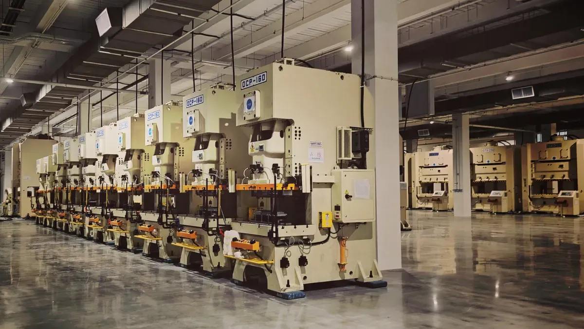
Hehua Machinery Technology (Kunshan) Co., Ltd. operates a manufacturing facility covering more than 17,800 square meters and employs over 160 people. Its integrated capabilities support customers in industrial machinery, automotive, rail transit, wind power, new energy equipment, and other high-end manufacturing sectors. With production and export services managed within its manufacturing organization, the company can support projects from engineering communication through fabrication, inspection, and delivery.
For customers evaluating Laser Welding for custom metal assemblies, the key is to verify that the process, material combination, joint design, and inspection plan match the component's actual requirements. A controlled approach to penetration, dimensional accuracy, and defect prevention provides a more dependable foundation for both prototype validation and repeat production.
Whether the project involves equipment frames, precision brackets, fabricated housings, or more complex welded assemblies, Hehua Machinery Technology (Kunshan) Co., Ltd. can help assess manufacturing requirements and coordinate the processes needed to produce metal components for industrial applications.


 AddressNo. 66 Xingpu Road, Lujia Town,Kunshan City, Factory Buildings 3 and 4
 en
 English
 繁体中文
 Italian
 Spanish
 Japanese
 Portuguese
 Korean
 Russian
 French
 German
 Estonian
 Arabic
 Indonesian


 Message